Hello and Happy Friday
My name is Christian, but you also may know me as c-po here at VyOS Project.
I'm an experienced (Embedded) Linux developer with a deep passion for open source networking.
Most of the time I design and operate Wide-Area-Networks on a global scale.
After hours, I am one of the VyOS Co-founders and platform architect.
This is the first article in an upcoming series of posts focusing on the "stretched layer 2" topic. Its primary focus is to answer the question if it is possible to leverage an Open Source solution to mimic the behavior/functionality of hardware vendors.
The background of this series is exclusively research and development and in no way I plan to rant against any other vendor. Also as this is very new functionality in VyOS please expect bugs, pitfalls, and all other things of funny behavior or missing features.
So what is this "EVPN" and why should I care?
The Internet Engineering Task Force (IETF) summarizes this technique in RFC8365 as "A Network Virtualization Overlay Solution Using Ethernet VPN (EVPN)".
EVPN is - simply speaking - a control plane enabled by the BGP multiprotocol extensions (much like other NLRI like IP VPN, VPLS/VPWS, labeled unicast, multicast). With an EVPN enabled network you can fulfill the requirements for scalable layer 2 environments based on an already existing, routed (layer 3) infrastructure. This means you gain the opportunity to provide layer 2 network connectivity on any interface of any device in your network. One can also build a datacenter network using the common CLOS network design (also called a "fabric" for how on a network diagram it kind of imitates a woven fabric). An EVPN enabled datacenter CLOS fabric has specific device roles due to the way the fabric is designed. There's two to three types of devices depending on how one wants to define the hierarchy in their design. The first device we will talk about is the "leaf" device. This device is the device that connects all of the end hosts or transit routers in a CLOS fabric. It is often considered to be the "edge" of a CLOS fabric. The second type of device is basically the backbone of the CLOS fabric, or the "spine" device. This device traditionally only connects to "leaf" devices and allows for the different "leafs" to be able to communicate and send transit traffic to each other.
Traditional Limitations addressed by EVPN
Older datacenter designs had a difficult limitation to work around when they were layer 2 designed. The (12-Bit) 4094 VLAN limitation was one of the primary problems to be solved by EVPN as now there is no longer any sort of tag limitation. The VXLAN transport overlay also gives you a total of 16,777,215 (24-Bit) independent layer 2 domains to be able to utilize as well. Therefore we should have sufficient identification/differentiation for the foreseeable future in any datacenter or any other type of network for multi-tenancy.
The Lab setup
As being a VyOS maintainer and highly interested in the topic of Open Source networking I asked my self some time back: How to get this new "EVPN/L2VPN, VXLAN" kid on the block actually working with VyOS itself and the FRR control plane we are leveraging?
All configurations leveraged in this post are already part of the 1.4 rolling release. By the time of this writing the 1.4 release train (named sagitta after the latin work for arrow) is the development train, so please expect unknown behavior - or lets rephrase that, bugs 🐞.
The lab is build on top of EVE-NG which I use for my networking experiments, it's always good to have an infrastructure you can break on purpose.
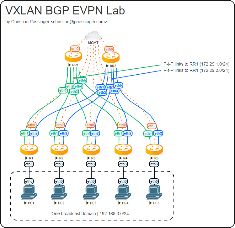
Topology
The lab consists out of two Route Reflectors (RR1 and RR2) which are used for redundancy, and at least two - we have five - VTEPs (VXLAN Tunnel Endpoints). A layer 2 VTEP is used to encapsulate the layer 2 traffic into VXLAN packets which are then send over the underlay to it's destination VTEP and then after decapsulating to it's final destination. VLAN tags are also stripped by default here as technically VLAN tags are not transported.
EVPN is a sub type of traditional MPLS services called L2VPNs. There are a few in there but for the sake of this we will omit the others. VXLAN is used in conjunction with EVPN as the transport protocol that carries the layer 2 packets that the EVPN PE (provider edge) routers transit. Currently we do not support EVPN with MPLS as the transport protocol. When one speaks of an overlay service (like the traditional MPLS L3VPNs, or L2VPNs) different words are used to differentiate different parts of the architecture. The two words are "overlay" and "underlay". Basically look at the "underlay" as the routing table in which the EVPN PEs (or VTEPs) will use to communicate to each other. Generally this will be seen as the main/master routing table that one sees when they do a "show ip route". You can populate the routing table that is used for "underlay" functionality with IS-IS, OSPF or BGP as routing protocols - whichever best fits your personal likings and/or network use case. The next word we will define is "overlay." Look at the "overlay" as a completely different (separate and private) network routing table that is used to enable some new service, in our case here an EVPN instance. When you have multiple EVPN routers that discover each other, and they discover that they are able to share NLRI (network layer reachability information, a fancy name for the type of information BGP is communicating) then they can build private and separate routing tables (or overlay networks). The overlay networks are able to work because the underlay beneath them allows for the EVPN PEs to send traffic that pertains only to those overlays safely to each other. So to recap, the "underlay" is a collection of network devices that are able to transport packets from any router to any other router. The overlay is a separate and private network that routers create by communicating with each other and sharing information on how to send traffic safely to each other that pertains only to that separate and private network.
Now, onto our example. In our example we solely rely on BGP and do not introduce any other routing protocol. We are using the concept of "BGP as IGP" in this design. We enabled support for up to four ECMP paths for load sharing - only two are in use at the moment.
Configuration
For redundancy, maintenance, and ease of use reasons every individual EVPN session is connected to both route reflectors. All VTEPs are sourced from an IP address assigned to a dummy interface so we can leverage multipathing and also allow other paths to take over in case of failure.
A dummy interface is the Linux/VyOS equivalent of a loopback interface.
set interfaces dummy dum0 address '172.29.0.1/32'
- R1 dum0 interface uses address 172.29.0.1/32
- R2 dum0 interface uses address 172.29.0.2/32
- R3 dum0 interface uses address 172.29.0.3/32
- ... and so on ...
The configurations used in the examples above can be found on GitHub for RR1 or RR2 and R1 to R5. These configurations are part of the projects CI/CD pipeline and are loaded during test for every published version.
BGP
VTEP configuration
Now it is time to establish our EVPN BGP peerings between the VTEPs and the Route Reflectors. The following configuration is used on R1 as it uses the network 172.29.1.0/31 as the Point-to-Point link from R1(eth1) to RR1(eth1) and network 172.29.2.0/31 as Point-to-Point link for R1(eth2) to RR2(eth1).
# Underlay information specifically here for BGP multipath
set protocols bgp 65010 address-family ipv4-unicast maximum-paths ibgp '4'

# Underlay information specifically here to announce dummy interfaces through BGP
set protocols bgp 65010 address-family ipv4-unicast redistribute connected

# Overlay information used by EVPN routers to announce all VNIs that are configured
set protocols bgp 65010 address-family l2vpn-evpn advertise-all-vni

set protocols bgp 65010 neighbor 172.29.1.0 peer-group 'evpn'
set protocols bgp 65010 neighbor 172.29.2.0 peer-group 'evpn'
set protocols bgp 65010 parameters log-neighbor-changes
set protocols bgp 65010 peer-group evpn address-family ipv4-unicast nexthop-self
set protocols bgp 65010 peer-group evpn address-family l2vpn-evpn nexthop-self
set protocols bgp 65010 peer-group evpn remote-as '65010'
We now have a solid connection and routes are learned via BGP used for the underlay population:
vyos@R1:~$ show bgp ipv4 summary
IPv4 Unicast Summary:
BGP router identifier 172.29.2.1, local AS number 65010 vrf-id 0
BGP table version 59
RIB entries 29, using 5568 bytes of memory
Peers 2, using 43 KiB of memory
Peer groups 1, using 64 bytes of memory

Neighbor      V      AS  MsgRcvd MsgSent TblVer InQ OutQ    Up/Down   State/PfxRcd PfxSnt
172.29.1.0    4   65010       43      27      0   0    0   00:00:23             13      3
172.29.2.0    4   65010       41      25      0   0    0   00:00:23             13      3

Total number of neighbors 2
The BGP configuration differs only in the used neighbor address for R2, R3, R4, R5.
Route-Reflector (RR) configuration
As this setup uses iBGP as IGP (Interior Gateway Protocol) it is not efficient to build up a full mesh for all participating peers, thus we leverage a route reflector. The reflectors only differ in the listen range statement.
By telling VyOS to listen for inbound BGP sessions sourced from a given prefix we do not need to create every session in advance. FRR handles this dynamically for us.
set protocols bgp 65010 address-family ipv4-unicast maximum-paths ibgp '4'
set protocols bgp 65010 address-family ipv4-unicast redistribute connected
set protocols bgp 65010 listen range 172.29.1.0/24 peer-group 'evpn'
set protocols bgp 65010 parameters log-neighbor-changes
set protocols bgp 65010 peer-group evpn address-family ipv4-unicast route-reflector-client
set protocols bgp 65010 peer-group evpn address-family l2vpn-evpn route-reflector-client
set protocols bgp 65010 peer-group evpn capability dynamic
set protocols bgp 65010 peer-group evpn remote-as '65010'
After the BGP configuration is applied to your reflector, you can see inbound connections and established neighborships by running the following operational level command from your CLI.
vyos@RR1:~$ show bgp ipv4 summary

IPv4 Unicast Summary:
BGP router identifier 172.29.1.8, local AS number 65010 vrf-id 0
BGP table version 19
RIB entries 29, using 5568 bytes of memory
Peers 5, using 107 KiB of memory
Peer groups 1, using 64 bytes of memory

Neighbor       V      AS  MsgRcvd MsgSent TblVer InQ OutQ    Up/Down   State/PfxRcd PfxSnt
*172.29.1.1    4   65010       12      19      0   0    0   00:06:46              3     15
*172.29.1.3    4   65010       24      38      0   0    0   00:16:47              3     15
*172.29.1.5    4   65010       26      40      0   0    0   00:18:41              3     15
*172.29.1.7    4   65010       26      40      0   0    0   00:18:25              3     15
*172.29.1.9    4   65010       25      39      0   0    0   00:17:21              3     15

Total number of neighbors 5
* - dynamic neighbor
5 dynamic neighbor(s), limit 100
EVPN configuration
Now as our underlay works as expected - which is probably the more complicating part - it's time to configure all parts related to EVPN/VXLAN - or in other words, create the stretched layer 2 overlay for R1 to R5.
Our route-reflectors only need to enable the new l2vpn-evpn address family for all our peers we bundle within the "evpn peer-group".
set protocols bgp 65010 peer-group evpn address-family l2vpn-evpn route-reflector-client
On all our VTEPs we need to extend our BGP configuration with two statements to forward all learned MAC address to the BGP network. This is done by configuring this on all VTEPs (R1-R5)
set protocols bgp 65010 address-family ipv4-unicast redistribute connected
set protocols bgp 65010 peer-group evpn address-family ipv4-unicast nexthop-self
VXLAN configuration
Now that all locally learned MAC address get forwarded to all other peers in the EVPN network it's time to spin up our VXLAN interfaces. As Linux predates the VXLAN RFC it uses a different default port (8472) so we adjust this to the standard IANA assigned port number. Out VXLAN interface is sourced from the dummy or loopback IP address we have configured for every individual node above. The Virtual Network Identifier (VNI) is the identifier used for this VXLAN connection. You can configure up to 16,777,215 VNIs.
set interfaces vxlan vxlan100 parameters nolearning
set interfaces vxlan vxlan100 port '4789'
set interfaces vxlan vxlan100 source-address '172.29.0.1'
set interfaces vxlan vxlan100 vni '100'
Connecting to the real world
Everything we have configured so far - beside the Point-to-Point links - had no real physical connection. As this guide intends to "stretch" or "overlay" a layer 2 domain across a number of VTEPs we now need to create the "bridge" from the VXLAN tunnel to the real ethernet world.
This is done by using one of the earliest and long existing features of VyOS - the bridge interface.
set interfaces bridge br100 member interface eth3
set interfaces bridge br100 member interface vxlan100
Validation
Display all the MAC addresses we have learned for VNI 100 by running "show evpn mac vni 100".
vyos@R1:~$ show evpn mac vni 100
Number of MACs (local and remote) known for this VNI: 3
Flags: N=sync-neighs, I=local-inactive, P=peer-active, X=peer-proxy
MAC               Type    Flags Intf/Remote ES/VTEP         VLAN   Seq #'s
50:00:00:01:00:03 local         br100                          1   0/0
00:50:79:66:68:08 remote        172.29.1.3                         0/0
00:50:79:66:68:07 local         eth3                               0/0
But how do we know which VTEP is responsible for reaching a certain MAC address? This can be done by using the build-in operational level command "show bgp l2vpn evpn route vni 100" which will provide us a list how packets are routed to reach their final destination.
cpo@R1:~$ show bgp l2vpn evpn route vni 100
BGP table version is 20, local router ID is 172.29.2.1
Status codes: s suppressed, d damped, h history, * valid, > best, i - internal
Origin codes: i - IGP, e - EGP, ? - incomplete
EVPN type-1 prefix: [1]:[ESI]:[EthTag]:[IPlen]:[VTEP-IP]
EVPN type-2 prefix: [2]:[EthTag]:[MAClen]:[MAC]:[IPlen]:[IP]
EVPN type-3 prefix: [3]:[EthTag]:[IPlen]:[OrigIP]
EVPN type-4 prefix: [4]:[ESI]:[IPlen]:[OrigIP]
EVPN type-5 prefix: [5]:[EthTag]:[IPlen]:[IP]

Network             Next Hop            Metric LocPrf Weight Path
*> [2]:[0]:[48]:[00:50:79:66:68:07]
                    172.29.0.1                         32768 i
                    ET:8 RT:65010:100
*>i[2]:[0]:[48]:[00:50:79:66:68:08]
                    172.29.1.3               0    100      0 i
                    RT:65010:100 ET:8
* i[2]:[0]:[48]:[00:50:79:66:68:08]
                    172.29.2.3               0    100      0 i
                    RT:65010:100 ET:8
*> [3]:[0]:[32]:[172.29.0.1]
                    172.29.0.1                         32768 i
                    ET:8 RT:65010:100
* i[3]:[0]:[32]:[172.29.0.2]
                    172.29.2.3               0    100      0 i
                    RT:65010:100 ET:8
*>i[3]:[0]:[32]:[172.29.0.2]
                    172.29.1.3               0    100      0 i
                    RT:65010:100 ET:8
* i[3]:[0]:[32]:[172.29.0.3]
                    172.29.2.5               0    100      0 i
                    RT:65010:100 ET:8
*>i[3]:[0]:[32]:[172.29.0.3]
                    172.29.1.5               0    100      0 i
                    RT:65010:100 ET:8
* i[3]:[0]:[32]:[172.29.0.4]
                    172.29.2.7               0    100      0 i
                    RT:65010:100 ET:8
*>i[3]:[0]:[32]:[172.29.0.4]
                    172.29.1.7               0    100      0 i
                    RT:65010:100 ET:8
* i[3]:[0]:[32]:[172.29.0.5]
                    172.29.2.9               0    100      0 i
                    RT:65010:100 ET:8
*>i[3]:[0]:[32]:[172.29.0.5]
                    172.29.1.9               0    100      0 i
                    RT:65010:100 ET:8
Conclusion
One of the initial questions I asked myself was it it would be possible at all for an Open Source system like VyOS to create such a modern and niche topology which a lot of people are talking about and also keep the configuration as simple as possible. The answer to this question is clearly: Yes it is!
We now have a standards compliant layer 2 overlay implementation available on our favorite Open Source routing platform.
Stay tuned!

Comments